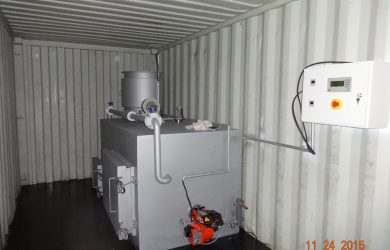
Containerized Incinerators

Model CA50 Feed Capacity Average 60 kgs per feed Burning Rate Average 70 kgs per hour Burning Time per Feed 1 …

Equipment Specification for Children & Maternity Hospital Charsadda

Designed to burn disposables that can and should be destroyed on-site. Theses wastes include infectious and contaminated “red bag.” Surgical dressings, plastic test devices and other wastesFast, complete, efficient waste disposalDual chamber combustion, Chambers insulated and lined with high temperature refractory. Programmable digital temperature controls, temperature indicators and charge recorder. Modulating control for fuel and air lowers fuel consumption. Minimum installation and start up timeAluminized steel jacket lined with refractory and firebrick. Monitors recorders and other accessory equipment should be available. Charging system:• Vertical charge door on primary chamber.• Pneumatic or hydraulic ram charging system. • Auto shut down of the door after charging.• Primary and secondary chamber temperature displayed and recorded (optional)Charging rate:• Up to 100kgs per hour of waste or red bag waste rated at 2200 BTU’s per kg.Fuel:-  Natural GasCapacity (Cubic Mtr): 1.65M3 or moreAve Capacity: 100kg per hourSecondary Chamber Capacity (CubicMtr) :3.88 or moreLength (mm): 1880 or betterWidth (mm): 1280 or betterHeight Incl. Flue (mm): 7700 or betterAsh  Door Opening (mm): 475×900 or betterMin. Operating temperature: 90 degree centigradeMax, Operating Temperature: 1350 degree centigradeResidency time in Second Chamber: 2 secTemperature Monitoring: Both for primary and secondary chambers.Loading SystemManual/semi-automaticWaste destruction efficiency:> 90% by weight Filter: Ceramic or other equivalent filters in order to reduce the induction of hazardous air pollutants, particulates, co,dioxin/furane into the atmosphere.De ashing system: Manual/semi-automatic.The System must be quoted complete with:-• Plumbing• Electrical panels• Civil works• Waste collection Trolleys …

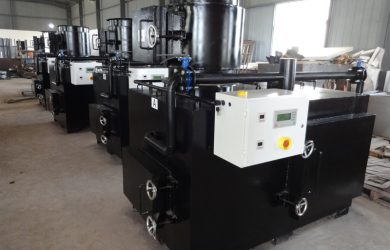
double chamber incinerators

Construction   Constructed from heavy duty mild or aluminized steel  or equal and approved equivalent                                                                 Refractory material liningLength 10 m above groundBore about 350mm diameterDischarge temperatures          About 850 0CEmissions   To comply with standards in section 9 of third schedule of the waste management regulations, 2006.    3.5       Electrical System   Control unit                                 Fully automatic with microprocessor based control                                                                      unit (PLC) automating all operations of the                                                                      incinerator. Capable of monitoring all incinerator parameters With large LCD or similar for display of all progressParameters  i.e. temperature of primary and secondary chambers, turbulence and timeWith status lampWith user of defined and differed programmed operating cycles for different type of loads/conditionsWith safety interlocks, display of errors and visible and audio alarms.System for continuous  emission monitoringIsolator switch                               Supply and install isolator switch 240V, 100A for the                                                                    incinerator unit, including all necessary cables 10mDistribution Board Supply and install distribution board. 100 A, complete with MCBs suitable for the rating of the incinerator unit and associated equipment.  Wiring   to be done according IEE regulations.Wiring Make provisions for wiring the isolator switch, Distribution Board control unit to Incinerator and all associated equipment inside to incinerator room.                                                                       Working length 20m.  Wiring to be done using PVC Sheath cable on steel conduits and trucking and in accordance with IEE regulationsFuel System                                    Supply and install storage fuel tank inside the incinerator room at an elevated position (about 1.5 m above the floor)                                                                 Fuel Tank                                         Tank capacity, 400 liters, constructed from preferable suitable metallic material or high temperature resistance materialFuel type DieselFuel Lines                                        Supply and install fuel lines, complete with fuel filters, pump, sight glass, fuel level and all other safety devices and connect from fuel tank to incinerator.                                                                         Working length , 20mFuel pipe material; Special copper pipes or similar                                                                        and approved materials

SUPPLY, INSTALLATION AND COMMISSIONING OF WASTE INCINERATOR – TECHNICAL SPECIFICATIONS

SUPPLY, INSTALLATION AND COMMISSIONING OF WASTE INCINERATOR – TECHNICAL SPECIFICATIONSThe Waste Incinerator is designed to burn Type IV of pathological waste and infectious, contaminated “red bag,” surgical dressings, plastic test devices and other wastes. General SpecificationsBurner:  2 burners (primary burner and second burner) Fuel: Oil Capacity (Cubic Mtr): 0.65 Ave Capacity: 60 kg per hour Fuel Consumption (ltrs / hr):13 External DimensionsLength (mm): 2300 Width (mm): 1220 Height Incl. Flue (mm) 7000 Door Opening (mm) 610 x 710 610 x 710OperationMin. Operating Temperature: 950 Max. Operating Temperature: 1320 Residency Time in Second Chamber: 5 sec Temperature Monitoring: YES Other clarificationEasy and safe operationLarge counter-balanced fill door with electrical    lockout.Automatic control system provides preset burn times and shut off. Reload light indicates to operator when it is time to recharge. Be required for burnout of final charge.  Low energy consumption levels Programmable digital temperature controls maintain temperature, assuring complete combustion while conserving fuel.  Pressure blower with modulating air control creates turbulence and distributes combustion air to secondary chamber.  Secondary burner with temperature activated modulating control provides fast preheat and   sustains high temperature performance at low energy consumption levels.  Charging rate  Up to 600kgs per ten-hour day of Type IV pathological waste or red bag waste rated at 2200 BTU’s per kg, based on batch loading twice daily.Thermocouples (2 pcs/ each thermocouple assembled on the unit )Thermocouples with pocket (1 pcs/each burner )Nozzles (2 pcs/burner)Nozzle line (1 pc/burner)Glass fibre (2 roll/size)Ignition electrode ( 2 pcs/burner)High tension cable ( 2 pcs/burner)Flame photometer (1 pcs/burner)Burner primary chamber (1 set)Burner secondary chamber (1set)Control panel parts (1 set)Fuse (1 pk from each rating )Solenoid valve (1 pcs/assembled on the unit)Burner oil filter  (10 pcs/burner)Fuel pump (1 pcs/burner)Shaft seal kit (1 set /shaft)Seal plate gasket ( 1 set / plate )Mechanical seal (1 set)Flue gas restricting  ring bricks (1set)Refractory cement (1 pk ) Shaft bearing (1 set)V belts (1 set)

Secondary Combustion Chamber (After burner)

The plant must have four distinct sections that demonstrate three principles of turbulence, residence time and temperature retention. The regulated sections may include but not limited to: 1. Overall plant layout 2. Feed chamber/charging 3. Primary combustion chamber 4. Particulate scrubbers 5. Acid gas scrubbers. 6. The stack/chimney. 7. Minimum capacity of primary chamber = 0.18 cubic metres 8. Burn rate (rate of waste incineration) = a least 20 kg per hour 9. Should have a full width counterbalance loading door allowing easy access to the main chamber for loading and removing ash. Supply, Installation and Commissioning of An Incinerator in Eastern Hydros [ Page 28  2.2 Feeding and Charging Controlled hygienic mechanical feeding that does not negatively influence the air temperature in the primary and secondary chambers of the incinerator shall be used. 2.3 Primary Combustion Chamber.  a) This chamber should be equipped with burners that use low sulphur fuel. b) The chamber should ensure a minimum exit temperature of 850 degrees centigrade.  2.4 Secondary Combustion Chamber (After burner)  a) Should be fitted with burners that use low sulphur fuel. b) Ensure secondary air supply is controlled. c) Ensure residence time is not less than two seconds. d) Ensure that the gas temperature as measured against the inside wall in the secondary chamber and not in the flame zone is not less than 1100 degrees centigrade. e) Ensure the emitted oxygen content of the emitted gases is not less than 11% f) Ensure both primary and secondary combustion temperatures are maintained until all waste is completely combusted.